Specifics of Handling Assembly Drawings |
  
|
Specifics of Handling Assembly Drawings |
|
This section describes main capabilities and design techniques of fragments and assembly drawings. Detailed description of fragment-handling steps is provided in further sections of this chapter.
Assembly drawing creation techniques
Before starting with creation of an assembly drawing, think through its structure. Try to define requirements to its parametric layout: what specifically will be subject to modifications in the future, what parts will make up the drawing, what is the expected hierarchy of fragments. The conclusions made at this preliminary analysis stage will define the preferable technique of the assembly model and fragment creation. Assembly design techniques differ in the ways of creating fragment files:
● "Bottom-up" development. This technique implies creating part drawings first, to be inserted in the assembly, in a conventional way in separate T-FLEX CAD documents. Assembly drawing creation in this case implies subsequent assembling of the necessary fragments. In the course of development, one has to accomplish the task of attaching part images within the assembly drawing.
● "Top-down" development. This technique implies that the part drawings originate from the assembly drawing. This means, the fragments are created in the assembly context. In this case, development start from creating the assembly drawing. Already created parts of the assembly drawing, including graphic lines and nodes belonging to fragments, can be used for creating new fragments. This approach simplifies creation of associative relations between the assembly fragments and the process of their attachment. The created fragments are saved into separate documents for further refinement and/or use in other assemblies.
The described techniques can be combined. For example, a fragment created and inserted in an assembly according to the "Bottom-up" approach, can later be edited in the assembly context. Vice versa, a fragment created in the assembly context, can later be used for creating other assemblies within the "Bottom-up" framework.
Ways of Attaching the Fragment Image to the Assembly Drawing
For placing the fragment image at a desired place in the assembly drawing, in the system T-FLEX CAD there are several different methods utilizing various tools depending on the problem being solved:
1.Inserting the fragment with the help of fixing vector. The fixing vector represents itself a special construction entity which serves as a two-dimensional coordinate system. When inserting the fragment into the assembly drawing, a user specifies location of the fixing vector, and the fragment image, connected to the fixing vector, is transferred along with that. The fixing vector is defined in advance in the fragment document (for more detailed description see the chapter «Bottom-Up Design»).

2.Inserting the fragment by fixing points. The fixing point represents itself an intersection of the horizontal and vertical construction lines the coordinates of which are specified by a pair of variables with special names x1…x9 and y1…y9. Accordingly, the number of fixing points can vary from 1 to 9. The entire parametric drawing of the fragment is constructed on the basis of the base construction lines determining the fixing points. When inserting such fragment, a user indicates a new location, and the parametric drawing of the fragment gets reconstructed depending on the new location of the base construction lines. This method is used when the fragment image (linear dimensions, shape, topology, etc.) has to be modified depending on the placement in the assembly drawing when position of the base fixing points is changed. For more detailed description see the chapter «Bottom-Up Design».

3.Associative/Non-associative fixing to elements of the assembly drawing. While designing by «Top-down» approach, upon creating a fragment in the assembly context drawing, a user can perform associative and non-associative fixing of the elements of the fragment to the elements of the assembly drawing (for more detailed description see the chapter «Top-Down Design»).


4.Without fixing (inserting «as it is», in absolute coordinates). When the fixing vector and the fixing points are absent while working with the «Bottom-Up» approach, and also, when all snaps are turned off while working with the «Top-Down» approach, the system puts the image of the drawing on the page of the assembly drawing without any changes. Each line or node of the fragment gets the same coordinates in the assembly drawing as the coordinates it had in the fragment document.
5.Use of special functions of variables. In some cases when inserting the fragment in absolute coordinates, the functions of the T-FLEX CAD variables can be used. For example, it is used for making the title block. In the parametric drawing of the title block the special functions that read the coordinates of the page borders of the assembly drawing are utilized. Then the coordinates are passed via the variables to the corresponding construction lines. Thus, the title block automatically takes the desired size in accordance with the specified page size of the assembly drawing.

Use of fragment variables
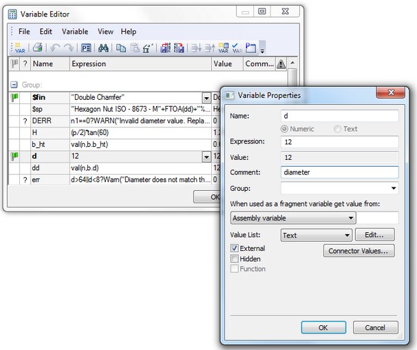
When inserting a fragment, one can define the values of the variables that define the fragment drawing. For this, the desired variables must be marked as external when creating the drawing of the future fragment. For example, to be able to define a circle radius of a fragment when inserting it in other drawings, assign an external variable (say, "R") to the circle radius when creating the respective construction circle. After that, any time when inserting this fragment into other drawings, the system will ask for the value of the variable "R", and then adjust the fragment image according to the input value.
The external fragment variables play an important role by relating the fragment parameters with those of the assembly drawing. For example, consider a drawing representing a shaft, whose diameter is assigned the variable "Diameter". Suppose, we need to mount a ball bearing on the shaft. A variable "d" was created in the ball bearing drawing that is responsible for the value of the ball bearing inner diameter. The variable "d" is marked as external. All the rest of the ball bearing parameters are interrelated in such a way that they are driven by the value "d". Now, as the bearing is inserted in the shaft drawing, the two variables can be related. After the above steps, modifications to the shaft diameter, that is, to the variable "Diameter" of the assembly drawing, will be automatically propagate as changes to the variable "d" in the fragment, leading to the desired adjustment of its image. |
|
An assembly variable name can be set same as an external variable name of the fragment (for details refer to the chapter "Variables"). When inserting a fragment in the current assembly drawing, if a same-name variable is found in the fragment as an assembly variable, the latter will be automatically assigned the respective external fragment variable.
For automatic specification of connections between the values of the fragment variables and the variables of other fragments in the assembly, the mechanism of connectors can be used (see below for details).
When working with a large number of external variables of a fragment, it is convenient to use configurations.
Configuration – is a named, stored in the document, collection of values of external variables for the fragments of the document and 3D geometry corresponding to these values. In the 2D document, only the values of external variables are stored in the configuration. The work with configurations will be described in more detail in the chapter “Auxiliary Tools for 3D Assemblies Modeling”.
If in the document of a 2D fragment, configurations are created, then, when inserting and editing the fragment, the user can select one of the fragment’s configurations. The values stored in the selected configuration will be automatically assigned to all external variables of the fragment.
The name of the used configuration can be specified as a variable. If the value of this variable changes, the system will select the corresponding configuration of the model and automatically modify the values of the fragment’s variables.
Visibility management of fragment drawing elements
A part drawing may contain an image that should not be included in the assembly drawing. Alternatively, we may need to use one or another portion of the same part drawing, depending on circumstances. (For instance, in one case we need to show the top view, while in the other – the front view.) Visibility of the fragment drawing elements inserted in the assembly can be controlled using layers or visibility levels. Two approaches are possible when using layers.
The first one is using a layer's own attributes ("Hidden when model is used as a Fragment", "Visible only when model is used as a Fragment"). This way does not allow defining several configurations of the fragment image based on the same drawing. Nevertheless, it allows hiding/showing the elements of the fragment part drawing that are definitely necessary in the part drawing, yet must be hidden in the assembly (or vice versa). This can be, for example, the part dimensions, the title block, etc.
The second approach is more flexible, and can be used when positioning the fragment by a fixing vector. The fixing vector parameters can relate the vector with selected layers (see chapter «Bottom-Up Design»). Thus, a number of part configurations (such as part views) can be obtained from the same drawing by creating several fixing vectors with different types of relation with the layers in the drawing.
Control over the visibility of the fragment drawing elements is done by using visibility levels in a way common across all drawing elements. This approach may require use of external fragment variables. Such external variables can be created in the fragment drawing, and then carried over to the assembly, in order to control the visibility levels of the fragment drawing. The visibility levels of the fragment drawing elements will obey the external variable settings both while editing in the assembly context and in detailing (in the exported assembly fragment instance).
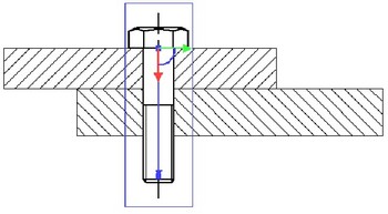
Hidden line removal in assembly drawing
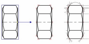
One of the important advantages of T-FLEX fragments is the hidden line removal mechanism when building an assembly from fragments. This allows, on one hand, creating a complete drawing of the desired part, while, on the other hand, "hide" the drawing lines that fall behind the image of other parts of the assembly drawing. The area in the drawing subject to hidden line removal is defined using a hatch. To remove hidden lines, you can use an existing hatch or create an additional invisible one (using the fill method "Invisible"). In the hatch parameters, set the flag "Use for hidden line removal". In this case, the invisible hatch will be hiding behind the objects with lower priority. Control over the visibility of a covered up element is done by setting an appropriate priority in its properties. If a fragment is supposed to cover assembly lines, then the fragment priority should be set higher than that of the assembly elements, which the fragment should cover. Vise versa, if the assembly lines should cover the fragment lines, then one would have to create a hatch in the assembly drawing itself, and then set its priority higher than the priority of the respective fragment. |
|
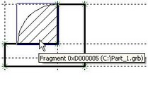
Let's review hidden line removal on the example of a shaft drawing and a ball bearing fragment. We need to create a hatch in the shaft drawing for hidden line removal. Upon inserting the fragment in the assembly, the ball bearing fragment image will be overlapping the shaft image. For the shaft image to cover the lines of the ball bearing, we need to set the priority of the ball bearing fragment lower than the priority of the hatch contour on the shaft. This can be done by the immediately at the time of inserting the fragment, or later, when editing it. |
|
Upon modifying the fragment priority, refresh the image by calling the command "RD: Update Model Windows" (by pressing <F7>). As a result, the image will appear as shown on the lower right diagram. |
|
Snapping the fragment elements
Even though the lines and other elements of a fragment are not part of the assembly drawing that includes it, those can be used as references for creating various elements of the assembly drawing. Ordinary lines of the fragment image (arcs and circles) can be used at the time when the object snapping is turned on. In this way, one can create new construction lines on top of the fragment graphic lines or dimension those, or attach any other detailing elements.
Besides the graphic lines, one can use the fragment nodes as references. To engage use of fragment nodes, you need to activate certain settings. The flag Fragment Nodes must be set in the command "SO: Set System Options" on the tab Snap > Priority. This setting allows creating assembly drawing elements that rely on the named fragment nodes or end points of graphic lines. In this way, the new nodes based on fragment nodes are created in the transparent mode.
If the image of the fragment is crowded with various elements, working in transparent mode may become somewhat difficult. In this case, you can turn off the discussed setting and work in the mode of forcing creation of necessary nodes based on a fragment:
1. The command "N: Construct Node" allows creating only the nodes that will later be actually used in the assembly constructions (a detailed description is provided in the respective chapter).
2. Named fragment nodes can be created automatically when inserting the fragment, provided that the flag "Create Named Nodes Automatically" is set in the system settings (the command "SO: Set System Options", the tab "Fragments").
Assembly BOM creation
Creation of bill of materials is one of the important steps in handling assembly models. Detailed description of handling BOMs is provided in chapter “Product Structure, Reports, Bills of Materials”.
For automatic filling of BOM records, you need to make sure, that the parts (fragments) of the assembly document contain sets of the relevant data. BOM data can be defined in the fragment part document in “Product structure” window at any stage of creation. You can specify the way of using the inserted elements (other fragments) and their data contribution in the product structure of assembly. This allows including in the product structure the data about inserted fragments or append data from product structure belonging to a fragment document. Defining an appropriate mode simplifies building bills of materials of multi-layer assemblies.
To obtain the BOM of the assembly document, you need to do the following steps:
1. Enter the BOM data in the product structure window in the fragment document.
2. In the assembly document, define the way of including the fragment in product structure, either in the fragment parameters or in the command “BI: Include in Product Structure” (“Tools|Report/Bill of Materials|Elements”).
3. Using the command “BC: Create Report/Bill of Materials”, generate the assembly BOM.
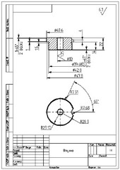
Detailing drawings based on fragments
When building an assembly, the fragment drawings may be modified according to the assembly parameters via modifications of the fragment external parameters or the whole drawing when using associative attachments. In this case, the fragment drawing files are not changed. However, if necessary, one can automatically create separate documents with the drawings of the fragment parts adjusted to the assembly parameters. We will refer to such drawings as detail drawings. One can create detail drawings for the whole set of parts making up the assembly drawing. Once created, a detail drawing does not maintain any relation with the source assembly drawing.
To get a detail drawing, use the option ![]() in the command "EFR: Edit Fragment" or the command "Open Part" in the fragment context menu.
in the command "EFR: Edit Fragment" or the command "Open Part" in the fragment context menu.
Upon calling the command, a new document window will be opened, with a copy of the fragment drawing loaded in it, with the external parameter values and associative relations inherited from the assembly. The new drawing will be named "Part" with a subsequent number, for example, "Part 1". This drawing will be treated by the system is a new document, with the system asking to define the name to save the drawing as upon an attempt to close the window.

Usually, detail drawings are used for printing out hard copies of the detail drawings that can be different from the original fragment drawing due to, for instance, modifications of the assembly variables. In such case, you don't even have to save a copy of the detail drawing into a file. This is convenient in the case when a parametric fragment used in the assembly has a corresponding fully furnished drawing. In such a case, upon creating the detail, the user instantly gets a complete set of new documentation for the desired part.
Exploding fragments
An inserted fragment can be exploded. By this operation, the fragment is removed, while instead the copies of all fragment elements are created in the assembly drawing that were deemed visible at the time of assembling.
The system can explode selected fragments in two ways, creating drawing elements with or without construction entities. In the first case, all parametric relations are preserved between the former fragment elements by carrying over all necessary construction lines for maintaining parametric relations of the former fragment drawing. In the second case, the fragment is transformed to a set of graphic lines attached to free nodes.
A fragment that contains nested fragments is exploded into the graphic elements and fragments that it contains. After using the exploding option, the obtained elements can be treated as usual, according to the type.
If some elements in the assembly drawing were attached to fragment elements (dimensions, construction lines, etc.), then, upon exploding, those will be re-attached to the elements created by the fragment explosion (nodes, construction and graphic lines).
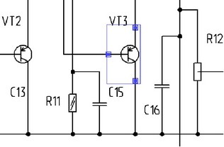
Use of connectors
When creating assembly documents, it is often necessary to relate parameters (variables) of the inserted elements with the parameters of the elements to which the attachment is made. Examples are: setting a ball bearing on a shaft, attaching a cap to a ball bearing, a shaft key to its slot, a nut to a bolt, insertion of a screw or being into a hole, etc. When inserting such elements, the user is required not only to define the main dimension parameters (diameter, length, etc.), but also precisely position the elements being inserted with respect to the target element (selection of the attachment point and direction). One of the ways of solving this task is using "Measuring" mechanism. This mechanism, however, often requires large amount of auxiliary preparations. Connector mechanism helps significantly simplify the procedure of assembling elements and minimize the number of actions required from the user.
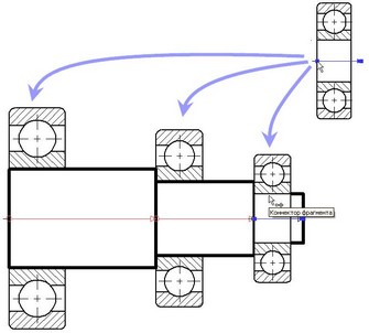
This mechanism is based on the concept of a "connector" which is a construction element serving as a reference for attaching other elements. In fact, a connector is a counterpart of a fixing vector or a target LCS for attaching 3D fragments. Its main difference from a fixing vector is that a connector serves for providing attachment reference to other model elements. Consider, for instance, use of a fixing vector for inserting a bearing image into an assembly drawing. Suppose, the image of the bearing should be attached to an axle. In this case, the connector should be attached to the axle image (fragment).
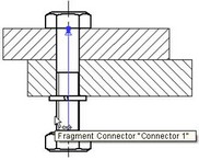
Besides the geometrical positioning (the origin position and the axes directions), a connector may keep additional information necessary for "snapping" to it other elements. This information is kept in the connector in the form of named values that can be constants or variables. The names of these values are used for specifying the values of the respective external variables of the fragments being snapped to the connector. For example, a connector placed on the axis of a hole, can have such parameters as the hole depth and the diameter. When inserting a pin in this hole, its diameter can be automatically defined by the value D kept in the connector. To achieve this, the external variable defining the in diameter should also be named "D".
There are a number of considerations when using a connector for snapping a fragment:
●A connector is a construction entity and may not be displayed in the main drawing, while it has to be selected when snapping a fragment to it.
●A connector may be located outside the viewable area of the drawing.
●Sometimes, it is convenient to use a connector for placing an element elsewhere. For example, when attaching a cap to a ball bearing, it is convenient to select the outer lines of the ball bearing. Meanwhile, the intended connector is lying on the ball bearing axis.
A concept of "associated elements" is introduced for dealing with such questions and for overall convenience. The list of such elements is stored in the connector. Associated elements are necessary for in-depth utilization of the object snapping mechanism when snapping to a connector. As the pointer approaches one of the image lines associated with the connector, the connector is automatically activated (highlighted in the screen), and the external variables of the fragment receive the values from the connector. The 2D fragment is automatically calculated with the new variable values and is snapped to the attachment point with the appropriate orientation.


All libraries of the standard T-FLEX CAD elements are already equipped with connectors and ready for their use. The required named values for linking with the connectors have been set in advance for the driving external variables.


